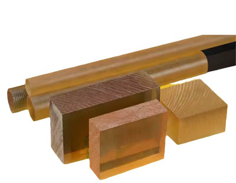
Engineering Plastic Rod: Properties, Applications, and Maintenance
What is an Engineering Plastic Rod?
Engineering plastic rods are high-performance Polymer materials manufactured in cylindrical form, designed to meet demanding mechanical, thermal, and chemical requirements in industrial applications. Unlike commodity plastics, these rods are formulated with enhanced properties through advanced polymer chemistry and reinforcement techniques. Common materials include:
Polyamide (PA/Nylon) - Available in PA6, PA66, and glass-filled variants with tensile strength ranging from 80-200 MPa
Acetal (POM) - Exhibiting low friction coefficients (0.1-0.3 μ) and excellent dimensional stability
Polycarbonate (PC) - With impact resistance up to 850 J/m (Izod notched)
PTFE (Teflon) - Operating temperature range from -200°C to +260°C
PEEK - Retaining mechanical properties up to 250°C continuous service
Standard diameters range from 5mm to 300mm, with tolerances typically held to ±0.1mm for precision applications. Lengths are commonly supplied in 1m, 2m, or 3m sections, with some manufacturers offering continuous extrusion up to 6m.

Key Characteristics with Technical Data
Engineering plastic rods offer superior performance characteristics compared to metal alternatives in many applications:
Mechanical Strength: Glass-filled nylon rods achieve tensile strengths up to 200 MPa, comparable to aluminum alloys while being 50% lighter
Wear Resistance: UHMWPE rods demonstrate abrasion resistance 8 times that of carbon steel in slurry applications
Chemical Resistance: PVDF rods withstand continuous exposure to 98% sulfuric acid at 60°C
Thermal Properties: PEEK rods maintain 80% of room temperature mechanical properties at 200°C
Electrical Insulation: PTFE rods have dielectric strength exceeding 20 kV/mm
Coefficient of Friction: Acetal rods exhibit dynamic friction coefficients as low as 0.15 against steel
Moisture Absorption: Polypropylene rods absorb less than 0.01% by weight in water immersion
Applications in Industry
The unique combination of properties makes engineering plastic rods indispensable across multiple sectors:
Food Processing Equipment
Conveyor system wear strips (UHMWPE rods with ASTM D-1044 Taber abrasion < 10mg/1000 cycles)
FDA-compliant Nylon 6 rods for meat processing guides
High-pressure washdown components (PPS rods with 1.5% water absorption)
Chemical Processing
PVDF rod liners for sulfuric acid storage (Corrosion rate < 0.1mm/year)
PTFE stirrer shafts in aggressive media
CPVC valve stems resistant to 93°C chlorine solutions
Automotive Components
Fuel system components (PA12 rods with UL94 V-0 flammability rating)
Bearing cages (POM rods with PV limit of 3 MPa·m/s)
30% glass-filled nylon rods for throttle body components
Semiconductor Manufacturing
PFA rods for ultra-pure chemical handling
Static-dissipative PEEK rods (surface resistivity 10^6-10^9 Ω/sq)
PTFE wafer carriers with Ra < 0.8μm surface finish
Maintenance Best Practices
Proper care extends service life and maintains performance characteristics:
Storage Conditions
Store horizontally on at least 3 support points to prevent sagging (especially for POM and PA)
Maintain temperature between 15-25°C and relative humidity below 50%
Protect from UV exposure - use opaque covers for outdoor storage
Machining Recommendations
Use carbide tools with 15-20° rake angle for optimal finish
Maintain cutting speeds between 100-300 m/min for most engineering plastics
Employ compressed air cooling rather than liquid coolants to prevent moisture absorption
Allow 24-hour stress relaxation period after machining before final assembly
Cleaning Procedures
Use isopropyl alcohol (70% concentration) for general cleaning
For FDA applications, validate cleaning with 3A Sanitary Standard 20-27
Avoid acetone with ABS or PC rods due to stress cracking risk
In-Service Monitoring
Check wear surfaces quarterly using dial indicators (maximum allowable wear typically 10% of wall thickness)
Monitor dimensional changes in humid environments - Nylon 6 can expand up to 2.5% at saturation
For load-bearing applications, replace at 50% of calculated creep deformation limit


